Choosing an induction sealing system is often treated as a question of generator power, but many sealing problems are not caused by the sealer itself. They start with the packaging specification or the way containers are handled on the line. A weak seal, a scorched liner, or a pack that leaks after distribution is usually traced back to a cap that sits crooked, a liner that does not suit the closure, or a conveyor that cannot present containers consistently.
This guide walks through the decisions that come before the purchase, from defining what the seal must do to testing the exact containers, caps, and liners you run, so the system you choose fits the line it will work on.
Define what the seal has to do
Before requesting quotes, be clear about why the pack needs sealing. Some packs need a tamper-evident feature that indicates whether a cap has been opened, and for most over-the-counter drugs in the US, that is a regulatory requirement. Others need a hermetic barrier designed to keep air and moisture out while preventing leaks under the expected storage and handling conditions.
That decision shapes the foil liner specification. Depending on its construction, a liner with a wax or paper backing can leave material in the cap and provide visible evidence of opening. A plain barrier liner can protect against moisture and oxygen without providing the same visible cue. Where both functions are required, the liner construction becomes more involved and may require a stronger, more carefully controlled bond. Buying a power unit first and then trying to make the liner fit the available process can lead to poor results and unnecessary testing.
Write the objective down in plain terms and secure agreement from quality and operations. A short statement such as ‘we need evidence of opening plus a leak-tight seal for a liquid fill’ gives vendors more useful direction than a generator power rating on its own.
Power and coil size should follow from that statement. Without a defined objective, vendors may quote against different assumptions, making fair comparison difficult. With it, buyers can ask whether the proposed setup will produce the required seal on the specified containers at the target operating speed. That provides a practical starting point for equipment selection.
Check container and cap fit first
Vendors can adjust power in small steps, but power changes will not correct a cap that does not sit squarely. Cap diameter and neck finish help determine the coil width required. If the coil is too narrow for a wide cap, the edges may run cool and leave areas of the seal weak. If it is too wide, heat can spread beyond the intended sealing area.
Foil liner choice forms part of that geometry question. Pulp-backed liners behave differently from composite structures, and each construction has its own operating window. A liner that requires relatively high heat may be a poor match for a cap material that softens at a lower temperature, and generator settings alone are unlikely to resolve that incompatibility. Involve cap and liner vendors early, then test the exact combination intended for production rather than relying on nominal specifications.
Product in the headspace introduces another variable. Liquid splash or powder dust on the sealing surface can interfere with the bond, while condensation associated with a cold fill can have a similar effect. Tall or lightweight containers can make the problem more pronounced because movement may throw product towards the foil. After trial runs, inspect the foil for residue, as spotting on an otherwise clean liner can indicate contamination during filling or handling.
Do not skip this check, even when the container and closure appear suitable during a static inspection.
The basic principle is straightforward: the coil creates an electromagnetic field that heats the foil without direct contact with the pack. For equipment buyers, the important point is that coil shape and distance can matter as much as the quoted power output.
Be realistic about speed and dwell time
Throughput helps determine the type of system required. A slower line with frequent changeovers has different requirements from one that runs the same container for long periods. Rather than quoting the maximum speed from a brochure, specify the speed the line can sustain for several hours, including normal stops and operator breaks.
Dwell time provides the link between conveyor speed and coil size. It is the period for which each capped container remains in the electromagnetic field. A faster conveyor reduces that time unless the coil is made longer or the system is configured differently. Consequently, two lines handling the same number of containers per minute may still require quite different sealing heads.
When dwell time becomes short, increasing heat can appear to be the simplest answer, but excessive heat may distort caps or scorch foil liners while still producing a patchy seal. A longer exposure window or a paired-head arrangement can provide a more controlled bond. It is often more useful to think in terms of exposure rather than power, because power without sufficient time is unlikely to create a consistent result across the whole sealing area.
Ask vendors to explain how they sized the head for the specified line speed and what happens at the slowest operating speed. A setup tuned only for maximum throughput may overheat packs when the conveyor slows. The suitable operating range should be identified during testing and recorded as part of the agreed process settings.
Bring the actual production containers to the trial. Published speeds alone do not demonstrate that a system will seal a particular pack consistently.
Compare system types for your line
Once speed and dwell time are clear, the hardware choice becomes easier to assess. Benchtop units suit laboratories and short runs where an operator positions each container by hand. They are generally easy to move and quick to set up, although seal consistency still depends on repeatable manual presentation.
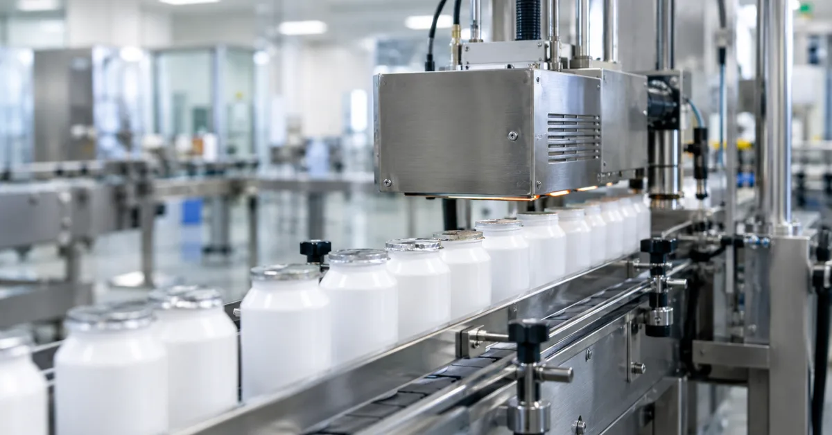
Intermittent systems pause each container beneath the coil using a stop or indexing section. Continuous systems keep containers moving beneath an extended head. Buyers can then choose between assembling separate components and specifying a purpose-built, turnkey induction sealing platform from a specialist vendor that supplies the generator, coil, cooling and controls as an integrated package.
Each approach has trade-offs. Separate components may reduce initial expenditure, particularly where suitable equipment is already available for reuse. A packaged platform may simplify integration because its main components have been selected to operate together and responsibility for system performance is clearer. This can reduce time spent during installation identifying whether a weak seal originates in the generator, coil, cooling arrangement, controls, or another part of the line.
Do not select equipment by footprint alone. A small head on a fast line may require higher settings and increase the risk of scorched liners. An unnecessarily long tunnel on a slow line occupies more space and may expose caps to excess heat during line stops unless suitable controls are fitted. Match the architecture to normal operating conditions, including the expected product mix. Changeovers and cleaning access also matter, so the design should favour the container sizes run most often without making less common formats impractical.
Where several sizes are handled, ask about tool-free changeover and repeatable settings. On a mixed production line, quick and reliable adjustment can be more valuable than maximum output.
Get container handling and alignment right
Container handling and alignment have a major influence on the success of an installation. A cap that enters tilted or off-centre is unlikely to seal evenly, even when power and dwell time are correct. Containers that wobble or tip also waste usable exposure. Stable presentation should therefore be treated as part of the sealing system rather than as a separate conveyor issue.
Inspect guides and belts before assuming that the coil is at fault. Side grips should hold containers upright without squeezing caps out of shape. Product spacing should prevent caps from clipping one another, while height adjustment should maintain a consistent gap between the cap and coil for every approved size.
Changes in conveyor speed can expose handling faults that static checks fail to reveal, so observe the line at full operating pace and again at crawl speed. A row of containers that looks orderly when stopped may begin to snake once the conveyor is moving. Caps can also shift slightly under vibration during an extended run, and even a small movement may leave one edge underheated while the opposite side appears satisfactory.
An intermittent line needs a clean, repeatable stop beneath the head. The stopping action should not jolt liquid onto the foil. A continuous line requires steady metering so that spacing remains even through the sealing area. In either case, the sealer cannot compensate reliably for containers that arrive crooked or move unpredictably beneath the coil.
Correct handling before adjusting power. Request a handling review as part of the quotation process, as a well-considered proposal should take account of line photographs, container samples, and operating conditions before settling on a power specification. A vendor that quotes power without asking about container stability may not have considered the complete application.
Sort controls and rejection before you buy
Modern production lines require more than controlled heating. The sealing system should integrate with the plant controls and identify faults without relying on operator guesswork. At a minimum, assess speed tracking and clear alarms for conditions such as missing caps and overheating.
Missing-cap detection and automatic rejection need particular attention. An unsealed container that continues downstream may create rework or lead to a customer complaint if it is not detected. A reject gate linked to the sealing system helps keep affected packs out of the finished batch. Confirm that the rejection logic also handles restarts correctly, as faults often occur immediately after a line stop or during the return to normal speed.
Data connections matter where performance is monitored across shifts, so confirm that the system can share its running status with the line controller in a format already supported by the plant. A long feature list is unnecessary if the essential signals are unreliable. The priority is dependable indication of running and fault states, together with a suitable way to log counts for quality records.
Ask to see the operator screens during a demonstration and establish whether authorised staff can change recipes without specialist support. The screen should also show why the most recent fault was triggered rather than providing only a generic alarm.
Clear screens can reduce training time and discourage unnecessary adjustments that move settings away from the approved specification. Controls will not correct poor container handling, but useful diagnostics can show where and when handling problems occur. Bring controls engineering into the review early and agree on the required signal list before installation begins.
Plan cooling, upkeep, trials, and service
Generators and associated electrical components produce heat during operation. The method used to remove that heat affects cabinet positioning, maintenance requirements, and the surrounding services. Fan-cooled cabinets need an adequate supply of reasonably clean air and enough space for airflow. Water-based cooling requires plumbing and routine inspection, but in some environments it may reduce reliance on ambient air, subject to the equipment design and enclosure rating.
Ask vendors about service arrangements in practical terms, including expected response times in the installation region and the spare parts commonly held by comparable sites. Clear answers on support, availability, and routine replacement items are often more useful for estimating ownership requirements than broad brochure claims.
The operating environment also matters, so record dust levels and temperature variation around the proposed installation point. A cabinet beside a dusty filler will face different conditions from one installed in a clean packing hall. Share photographs and cleaning procedures with potential vendors so that cooling provisions and enclosure specifications reflect the actual site rather than assumed ideal conditions.
Complete the selection process with a documented trial using the intended containers, caps, and liners. Run the system at the normal production pace and at the expected upper and lower speeds, then assess seal appearance and leak resistance using the agreed quality checks. Retain samples from the start and end of the run. Recorded trial results provide a sounder basis for comparing quotations than opinion or a brief demonstration.
If results vary across the speed range, review container handling and dwell time before increasing power. Small adjustments in those areas can often stabilise the sealing process without placing additional heat stress on the cap or liner.
A suitable system follows from a clear seal specification, a compatible container closure system, and stable container handling. Address those requirements first, and induction sealing is more likely to become a dependable part of the wider packaging line rather than a recurring production problem.